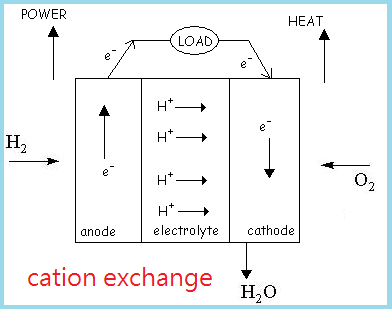
Fuel cells are devices that convert chemical energy into electrical energy in the presence of a fuel source, usually H2 gas, and an oxidant, or O2. Hydrogen is currently the most suitable fuel source not only because it is the most abundant chemical element in the universe, but also possesses highly flammable properties. The two common types of fuel cells known are cation exchange and anion exchange fuel cells.
A fuel cell consists of a negative electrode (anode), a positive electrode (cathode), and an electrolyte sandwiched in between the two electrodes. Fuel gas, or H2 for SOFCs, is transported to the anode through the anode-electrolyte interface, where the following half equation occurs:
H2(g) → 2H+ + 2e- (oxidation)
As electrons leave H2, they travel out of the anode and through an external circuit where work is performed, and finally arrives at the cathode where they are picked up by O2 gases, shown in the following half equation:
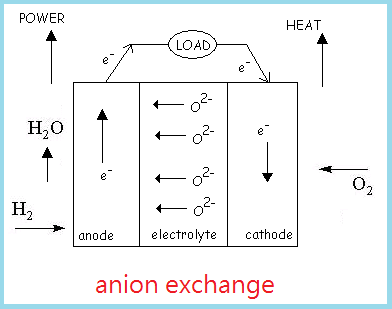
O2(g) + 4e- → 2O2- (reduction)
From the two half equations, we can obtain an overall equation as follows:
O2 (cathode) + 2H2 (anode) → 2H2O + heat
Thus the overall reaction releases H2O as a byproduct. Reaction results from an anion exchange fuel cell are the similar to a cation exchange fuel cell, except that O2- ions diffuse through the electrolyte to join with H+ ions to form H2O.
 |
 |
In solid oxide fuel cells, an interconnector consisting of channels is placed in between each set of anode-electrolyte-cathode combination, allowing fuel and air flow through each channel for the reactions to occur. The two most common types of geometries are planar and tubular structures. Planar structures allow a greater overall efficiency than tubular structures, but have sealing issues due to high operating temperatures, in which is currently one of the greatest challenges. Since reactions in SOFCs occur only at elevated temperatures, the choice of materials for each component is also critical. A large temperature range increases thermal stress, which may lead to micro-cracks in the materials and therefore decrease the area of contact between electrodes and electrolyte, resulting in reduced efficiency. Most SOFCs are composed of ceramic based with lanthanum strontium chromite interconnectors, lanthanum strontium manganite (LSM) cathodes, nickel zirconia ceremet anodes, and zirconia yttria electrolytes. The following table summarizes the thermal properties of each material.
| Material |
Thermal Conductivity, k (W/mK) |
Cp (J/molK) |
Density, ρ (kg/m3) |
| Cathode |
2.0 |
623 |
4930 |
| Electrolyte |
2.7 |
623 |
5710 |
| Anode |
2.0 |
623 |
4460 |
| Interconnector |
13 |
800 |
7700 |
Planar Geometries
Three major types of flow are studied in planar square-geometries: co-flow, counter-flow, and cross flow. Co-flow and counter-flow have the same geometries with the only difference in flow directions between the air and the fuel. A perpendicular cross-flow design was also developed to compare the power generation and temperature range of the materials with the other two. Although ceramics are able maintain their structural integrity at high temperatures, they have brittle properties and may easily fail due to a wide temperature range that causes difference in thermal expansion. This may lead to an increased thermal stress to be greater than the yield stress of the material, resulting in failure. Therefore different flow types are studied to determine the most suitable flow that not only prevents a large difference in thermal expansion, but also maintains enough overall system temperature to allow electrochemical reactions to occur. By altering the temperature of input fuel and air, an overall temperature range and the output temperatures can be determined through modeling. Modeling is important because theoretical calculations may not be able to take all the assumptions into account. Modeling also helps us to confirm that previous assumptions made are correct. However, because of the high production cost and difficult modeling environment at elevated temperatures, computer programs and softwares are used to model SOFCs. One of the most common types of modeling program used is Fluent, which incorporates geometries developed in Gambit to execute a modeling design.
Experimental Method
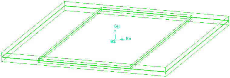
Fluent is a computational fluid dynamics (CFD) software that models three-dimensional fluid flows and implements energy transfer as well as thermal properties associated with fluid temperatures and flows. It also contains other physical functions such as mass transfer and momentum. In this model, we will make close observations on how changes in flow rate and thermal properties affect the temperature range between the inlet and the outlet of a single unit found in SOFCs. We will model and compare co-flow and counter-flow geometries by creating a planar geometry on Gambit. The model that will be examined has a square planar geometry with 97.6 mm on each side with total channel area of 0.54 cm2, or equivalent to 18 channels evenly spread out. The figure below shows the geometry used for modeling. All of the individual channels on the interconnector are merged into one with equivalent cross-sectional area due to difficulty in creating a proper mesh, in which the eighteen individual channels created much more skewness and this may result in increased residue when iterating. However, other geometries remained the same, including the thickness of the electrolyte to be 0.15 mm, and thicknesses of the anode and cathode are 0.05 mm each.
| Material and Initialization |
Properties |
| Air Inlet |
8.72 e-5 kg/s |
| Fuel Inlet |
2.206 e-6 kg/s |
| Air Temperature |
800 K |
| Fuel Temperature |
1173 K |
| Cathode Material |
Lanthanum Strontium Manganite |
| Anode Material |
Nickel Zirconia Ceremet |
| Electrolyte Material |
Zirconia Yttria |
| Interconnector Material |
Lanthanum Strontium Chromite |
 Co-flow Model Co-flow Model |
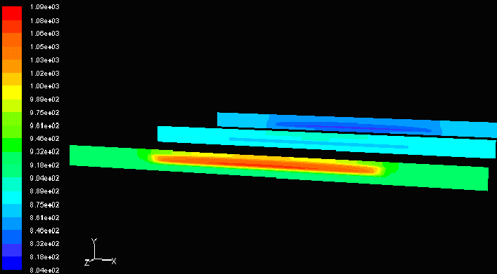 Counter-flow Model Counter-flow Model |
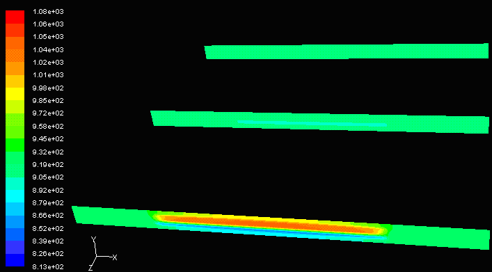
The temperature difference between the inlet and outlet is greater in counter-flow models. Although this allows more heat exchange because counter-flow allows a greater relative velocity between the fuel and the air, the large temperature difference creates non-linear thermal expansion throughout the cell unit. Sections with high temperature expand more than sections with low temperature. The expansion increases stress on neighboring molecules, and this may result in material failure if the thermal stress exceeds the yield stress of the material. Ceramics are brittle materials with low yield stress, therefore co-flow may be the preferred design.
Similarly, if there is a very large temperature difference between air and fuel inlets, a non-linear thermal stress and expansion may result, even if in co-flows, and the temperatures at the two ends are very different. As flow reaches the outlet, an equilibrium temperature is reached. This temperature is approximately the average of both temperatures, depending on flow velocity. Therefore this is one of the main reasons why air and fuel temperatures should not be extremely different. Also, for extreme temperatures, an overall system temperature would be lower. Since SOFCs only react at high temperatures of 1000K, an overall system temperature of 500K would not be able to drive electrochemical reactions in the anodes and the cathodes.
However, co-flow may not be the most efficient model. In fish gills, blood and water flow create a counter current with each other, therefore increasing the O2 diffusion between water and blood. This maximizes O2 concentration in the fish’s blood. From this analogy, it can be assumed that co-flow is less efficient than counter-flow. Since counter-flows increase thermal stresses in SOFCs, a third model, cross-flow, is developed to maximize efficiency and minimize thermal stress (theoretical assumption).
To further investigate why ceramics are the most suitable material, a comparison between aluminum and ceramics can be made. Figure below shows the temperature profile from the inlet to the outlet of a cell unit made from aluminum. The only obvious temperature difference is located at the entrance, in which the inlet fuel temperature and inlet air temperatures are 1173K and 800K, respectively. Since aluminum is a good conductor, the temperature reaches equilibrium very quickly, therefore a large amount of heat is lost and electrochemical reactions would not be able to proceed. To maintain an overall internal system temperature of over 1000K, better insulation is needed. Choice of materials is also dependent on its structural integrity at elevated temperatures. Metals such as aluminum have a melting point of 660.37 °C, or 933.52K, which, if used on SOFCs, would be unable to hold the structure.
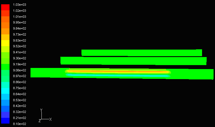 Co-flow, Aluminum Co-flow, Aluminum |
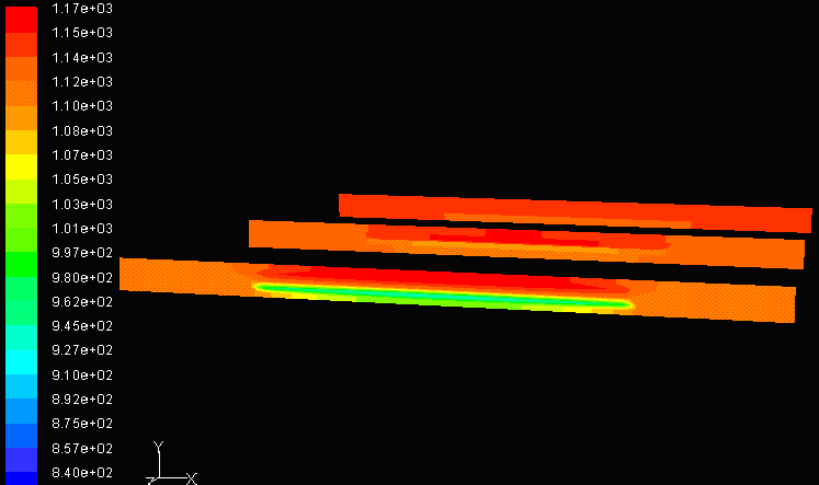 Co-flow, Equal Air and Fuel Mass Flow Rate Co-flow, Equal Air and Fuel Mass Flow Rate |
While flow direction is important, the choice of mass flow rate through air and fuel channels is critical. Flow rate of air and fuel determines the relative velocity between the gases inside interconnector channels. If both channels have the same flow rate, the relative velocity between fuel and air would be zero. This then reflects back to the fish and gill analogy, where zero relative velocity is less efficient. Figure to the right above shows a simulation of a model with zero relative velocity. It can be observed that the temperature remains relatively high and constant throughout the cell. If this is modeled as a heat exchanger, the temperature profile shown in the Co-flow Model would allow a higher efficiency because ΔT is greater between the inlet and outlet, therefore co-flows with different inlet velocities is preferred.
Fuel cells in general have a large capacity for improvements. With the high operating temperatures, solid oxide fuel cells are quite difficult to implement in many aspects such as vehicles and portable energy sources. In addition, creating an environment of elevated temperatures for electrochemical reactions to take place requires large amounts of input energy. SOFCs would be more feasible if they can operate at lower temperatures.
Analysis show that counter-flow is the most efficient configuration but causes non-linear thermal expansion that creates micro-cracks in brittle ceramics. Further research can be done to increase the ductility of the material and simultaneously maintain its structural integrity at very high temperatures. Also, SOFCs do not have to function alone. A hybrid system consisting of SOFCs, heat exchangers, and heat engines can be combined to generate and additional power.


